


When evaluating an LED display wall, you’ve likely come across terms like “common anode” or “common cathode.” But what do they mean? This article explains what each one means, how they compare, and why the difference matters for any serious LED video wall project.
What Is Common Anode LED Display Technology?
In a common anode (CA) configuration, all RGB LED anodes, i.e., the positive terminals, are tied together and share a single common positive voltage. Each LED cathode, the negative terminal, is individually connected to the driver IC.
Since the supply voltage is shared across all color channels, it cannot be adjusted per LED. That voltage must also satisfy the highest forward voltage requirement among the RGB LEDs, typically green or blue. Red LEDs, which often have a lower forward voltage, operate with a larger voltage gap between the supply and what they actually need. That gap is dissipated as heat in the driver IC.
What Is Common Cathode LED Display Technology?
In a common cathode (CC) configuration, all LED cathodes share a single common ground, while each LED anode has its own individual connection to the driver IC.
The key distinction is that the power supply for each LED can be adjusted independently. Rather than forcing every LED to operate at a fixed voltage ceiling, the common cathode configuration lets the driver IC deliver precisely the voltage each LED requires. Think of it as a smart power distribution system that serves each LED exactly what it needs, rather than running everything from the same tap.
Common Anode vs Common Cathode: What Are the Differences
The differences between common anode vs common cathode come down to five aspects:
1. Circuit Connection
A common anode configuration uses a shared positive terminal with individual cathode control per LED.
A common cathode design uses a shared negative terminal with individual anode control per LED.
2. Current Direction
In a common anode circuit, the path goes from the LED anode through the LED cathode, then through the driver IC and finally to ground.
In a common cathode circuit, current flows from the driver IC through the LED anode, then through the LED cathode and finally to ground.
3. Energy Efficiency
Common cathode technology, by accurately matching voltage to each LED’s actual requirement, delivers lower power consumption and less heat.
Common anode technology must set a higher voltage to satisfy all LEDs across the panel. The LEDs that don’t need the full voltage end up converting that excess into heat. On a large LED video wall, that waste adds up quickly.
4. Color Performance
In a common-cathode system, each color channel can be driven with a voltage closer to its own forward-voltage requirement. This gives the driver IC more favorable conditions for constant-current regulation and can improve color accuracy and grayscale performance, especially at low brightness.
In a common anode system, the voltage gap between the fixed supply and each LED’s forward voltage differs from channel to channel. The driver IC has to compensate for those gaps while still regulating current, which makes fine current control harder to maintain.
5. Initial Cost
Common cathode LED display technology requires high-precision driver ICs and a more complex circuit design, which raises the production costs of LED walls.
Common anode systems can rely on general-purpose chips, which simplifies circuit design and keeps the initial price lower.
| Feature | Common Anode (CA) | Common Cathode (CC) |
| Shared Terminal | Positive (Anode) | Negative (Cathode) |
| Individual Control | Cathode per LED | Anode per LED |
| Current Direction | Anode → Cathode → Driver IC → GND | Driver IC → Anode → Cathode → GND |
| Energy Efficiency | Lower with fixed voltage, more waste | Higher with precise voltage per LED |
| Color Performance | Good | Superior, especially at low brightness |
| Heat Generation | Higher | Lower |
| Driver IC Complexity | General-purpose chips | High-precision ICs required |
| Initial Cost | Lower | Higher |
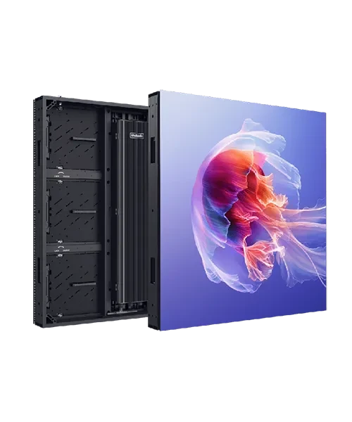
Common Cathode in Real-World Applications: Unilumin UpanelⅡ
What does common cathode LED display technology look like in a real product? The Unilumin UpanelⅡ is a compelling example.
The UpanelⅡ adopts Common Cathode & Flip-Chip technology, combining ultra-high stability with high luminous efficiency and low power consumption. Available in pixel pitches of P0.9, P1.2, and P1.5, it targets professional environments such as broadcast studios, control rooms, and conference spaces.
By accurately delivering the precise voltage each RGB chip requires, the UpanelⅡ saves around 40%–60% in power consumption compared with traditional SMD designs. Its front-maintenance structure, wireless cabinet connections, and intelligent sleep mode (5W/panel) further reduce operating costs and downtime, making it an ideal choice where image quality, reliability, and TCO all matter.
Conclusion
When choosing between common anode and common cathode technology, the decision ultimately comes down to priorities. For demanding environments where energy efficiency, color precision, and long-term reliability matter most, common cathode holds a clear advantage — and products like the Unilumin UpanelⅡ demonstrate exactly what that advantage delivers in practice.